skule.sormo.no
ORG NR 885 947 522
ESP mikrokontrollere
ESP 32 kontroller
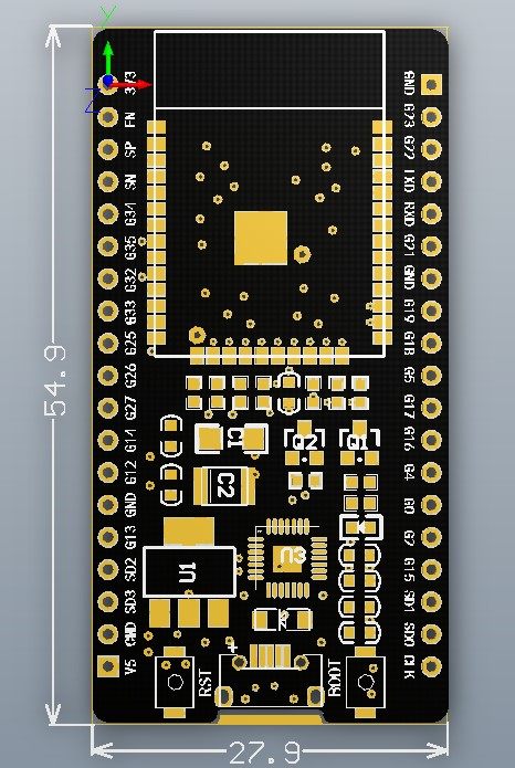
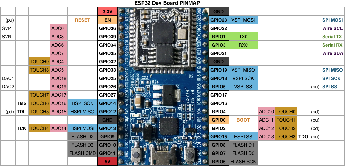
 Dette kortet er for de avanserte. Det har prossesorkjerner, en low power prosessor, WiFi og Bluetooth BLE. Den betjener de fleste serieprotokoller, har mange digitale og analoge inn- og utganger. Det er funksjonene som velges hvilke utganger som brukes. ;Man må unngå å velge funksjoner som bruker de samme utgangene.
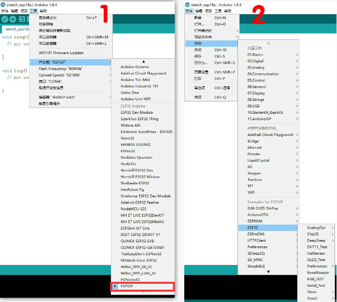
Kort: ESP32 Dev Module (ESP32 Arduino)
Installasjon: Last ned driver, lagres på Dokumentmappen for Ardruino i en egen ha Hardware- mappe der. I tillegg må programme get.exe kjøres i mappen Arduino/hardware/espressif/esp32/tools-mappen som administrator. I tillegg må Python 2.7.14 installeres.
OTA-funksjonen virker ikke fullt ut for ESP32.. Se også her
Vær oppmerksom at analogWrite() brukes ikke for ESP32. I stedet brukes ledcWrite(channel,duty). Den må initialiseres med ledcSetup og ledcAttachPin. Se mer info under.
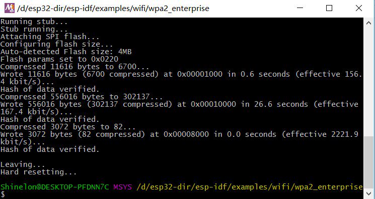
Programming guide Hjemmeside Espressif Systems Kolban technical tutorials PCBReflux's ESP32 Videos Flashdownloader
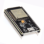
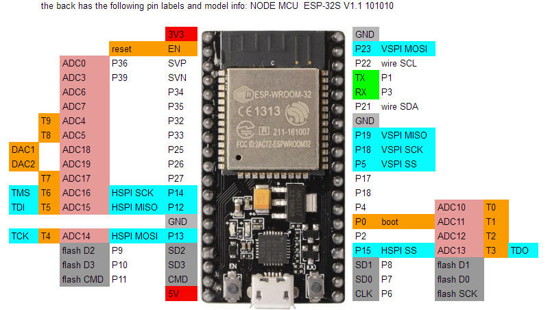
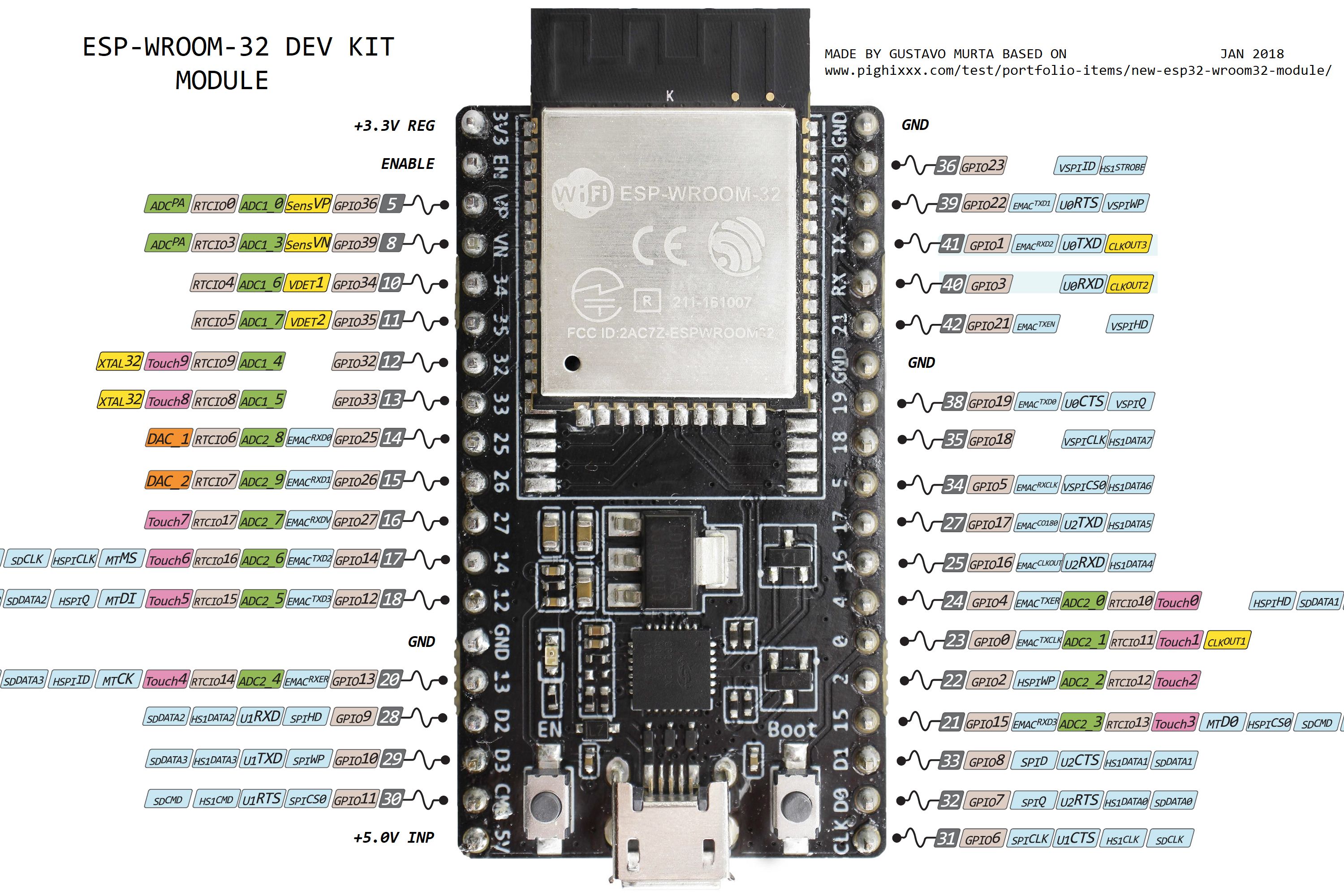
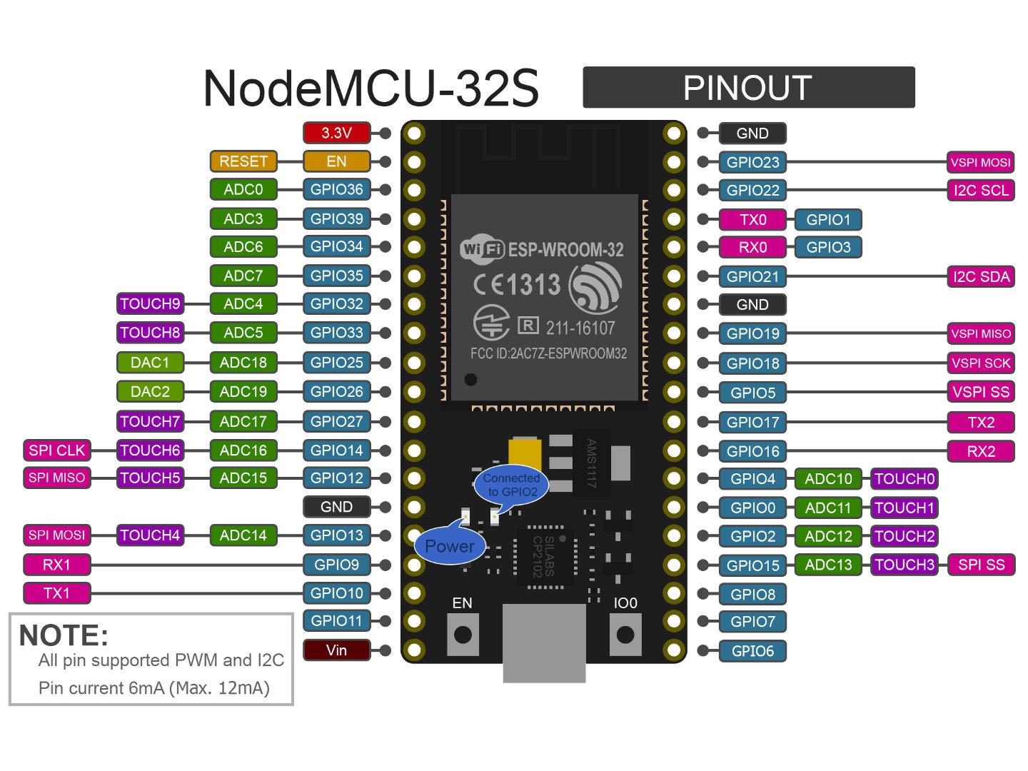
ESP32 ESP-32S NodeMCU Development Board 2.4GHz WiFi+Bluetooth Dual Mode
Funksjoner
- SPI
- GP-SPI
- Parallell QSPI
- SDIO
- SD
- MMC
- Ethernet MAC
- I2C
- I2S
- UART
- LED_OWM
- Remote Control Peripheral
- MCPWM
- Pulse_CNT
- 64-bit Timers
- Watchdog Timers
- eFuse Controller
- AES Accelerator
- SHA Accelerator
- RSA Accelerator
- Random Number Generator
- Flash Ecryption/Decryption
- PID/MPU/MMU
- PID Controller
- On-Chip Sensors and Analog Signal Processing
- Capasitive touch Sensor
- SAR ADC
- Low Noice Amplifier
- Hall Sensor
- Temperature Sensor
- DAC
- ULP Co-prosessor
- RTC_I2C Controller
- Low-Power Management
 Data replication SkyDrive link Download: https://pan.baidu.com/s/1nvFfIeX password: BCCC
The ESP-WROOM-32 is a versatile Wi-Fi + BT + BLE MCU module that is powerful, versatile and can be used for low power sensor networks and demanding tasks such as voice coding, audio streaming and MP3 Decoding and so on.
The core of this module is ESP32-D0WDQ6 chip *, with scalable, adaptive features. Two CPU cores can be individually controlled or powered on. The clock frequency is adjustable from 80 MHz to 240 MHz. The user can cut off the power of the CPU and use the low-power coprocessor to continuously monitor the status of the peripherals or whether some of the analog values exceed the threshold. ESP32 also integrates a wealth of peripherals, including capacitive touch sensors, Hall sensors, low noise sensor, SD card interface, Ethernet interface, high-speed SDIO / SPI, UART, I2S and I2C.
CPU and memory
The ESP32-D0WDQ6 has two low-power Xtensa® 32-bit LX6 MCUs. On-chip storage includes:
• 448 KB ROM for program startup and kernel function calls.
• 520 KB on-chip SRAM for data and instruction storage.
• 8-KB SRAM in RTC, or RTC Slow Memory, can be accessed by the coprocessor in Deep-sleep mode.
• 8-KB SRAM in RTC, RTC Fast Memory, which can be used for data storage and access by the host CPU when RTC starts in Deep-sleep mode.
• 1 kbit eFuse, where 256 bits are system-specific (MAC address and chip set); the remaining 768 bits are reserved for user applications, including Flash encryption and chip ID.
• ESP-WROOM-32 integrates 4MB of SPIFlash
Support Arduino IDE (providing video tutorials)
analogWrite() brukes ikke i ESP32. I stedet bryes ledcWrite/channel,duty).
Før de kan brukes, må de initialiseres med
ledcSetup(LEDC_CHANNEL,LEDC_BASE_FREQ, LEDC_TIMER_BIT) og
ledcAttachbPin(LED_PIN,LEDC_CHANNEL)
hvor
LEDC_CHANNEL : en av de 16 tilgjengelige timers.
LEDC_BASE_FREQ: Oppløsning
LEDC_TIMER_BIT: timer bit oppløsning, må være minst 12 bits
LED_PIN: pin som tilkobles
Eksempel på kode:
// use first channel of 16 channels (started from zero)
#define LEDC_CHANNEL_0 0
// use 13 bit precission for LEDC timer
#define LEDC_TIMER_13_BIT 13
// use 5000 Hz as a LEDC base frequency
#define LEDC_BASE_FREQ 5000
// fade LED PIN (replace with LED_BUILTIN constant for built-in LED)
#define LED_PIN 5
void ledcAnalogWrite(uint8_t channel, uint32_t value, uint32_t valueMax = 255) {
// calculate duty, 8191 from 2 ^ 13 - 1
uint32_t duty = (8191 / valueMax) * min(value, valueMax);
// write duty to LEDC
ledcWrite(channel, duty);
}
void setup() {
// Setup timer and attach timer to a led pin
ledcSetup(LEDC_CHANNEL_0, LEDC_BASE_FREQ, LEDC_TIMER_13_BIT);
ledcAttachPin(LED_PIN, LEDC_CHANNEL_0);
}
void loop() {
// set the brightness on LEDC channel 0
ledcAnalogWrite(LEDC_CHANNEL_0, brightness);
......